Valve Shim Installation
Installing Valve Spring Shims Without Removing Cylinder Heads:
The first RPM limitation on a stock motor is valve float at ~4400 RPM (different on each motor). Valve Float is a condition where the valves are opening and closing at such a high rate that the valve springs fail to fully close the valves for the cylinder, allowing them to float during the stroke cycles. This condition could possibly result in valve-piston contact and engine damage. To allow the motor to run at a higher RPM, you can add shims under the valve spring, increasing the spring pressure and eliminating the risk of valve float. Iron Mountain heads designed for higher RPM operation already have these shims installed (you will see them under the valve spring). BPS sells these shims as a High Rev Kit.
If installing CDI High Rev Coils (4700 Rev Limit) on a stock motor, you will need to install the shims to allow motor operation up to ~4500 RPM. Note- these shims from BPS are not just washers, they are specific thickness designed to add a precise amount of valve spring pressure.
Tools/Parts Required:
Tarp, 10mm Ratchet, Spark Plug Socket, Wooden Dowl, 5' length of 3/8 climbing rope (no loose fibers), shop rags, eye protection, Valve Spring Compressor tool, Valve Shims, and Torque Wrench. To reset the valve lash- 0.004-0.006 feeler gauge, 13mm wrench, T-40 Torx driver
Prepare your work area, there are small components involved so its advised to lay a tarp down under the motor to catch any parts if dropped.
1) Remove the spark plugs from both cylinders.
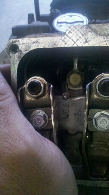
2) Remove the valve cover on one side of the motor. Engage the clutch or turn the crank shaft until the piston is on the compression stroke (put your finger in the spark plug hole until you feel the piston pushing air out of the hole on the compression stroke). Use the wooden dowel in the spark plug hole to gauge the piston position and turn the crank until the piston is 1/4" past top dead center. Both valves should be closed (slack on both rocker arms). Press down with the palm of your hand on the valve end of the rocker arm and move the push rod out from under the adjuster on the end of the rocker arm. Remove the rocker arm stud (10mm) and rocker arm and set aside the push rod with that rocker arm as a set. Remove the other push rod / rocker arm and set aside together so you can reinstall on the valve it was originally installed.
Push on the rocker arm to remove the push rod:
3) Reinsert the wooden dowel in the spark plug hole and engage the clutch or turn the crank shaft in reverse to move the piston in the cylinder to the bottom of its stroke.
4) Feed the length of rope into the spark plug hole. Tie a knot at the end of the rope so you do not loose it in the cylinder (just in case). The rope will support the valves so they do not drop into the cylinder or strike the piston when the valve spring is compressed.
5) Rotate the crank shaft forward until you feel resistance and the rope is fully compressed in the cylinder.
6) Insert a shop rag to completely block off the area in the head where the push rods go. Insert a piece of shop rag over the small oil drain hole in the front of the intake valve. This is important so you don't drop the small valve keepers into the motor.
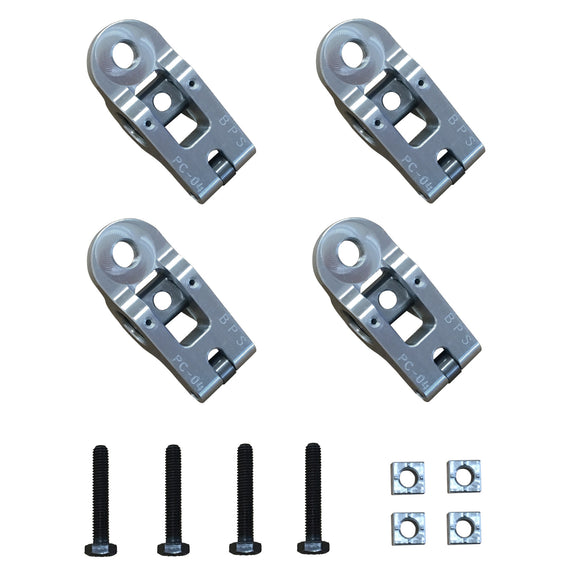
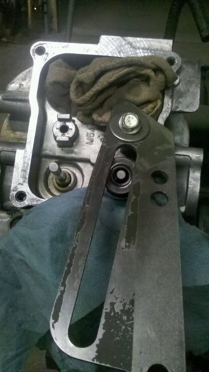
7) Install your valve spring compress tool. There is a Briggs part number for this tool (PN 19347) or aftermarket tools from the auto parts store meant for small engines (note- most of the tools common at auto stores are intended for much larger valves and do not work well for this application). The tool is a length of stock that has a hole on one end and a larger hole/slot that will fit over the valve stem. Pictured here is an old trim bracket that works very well for this operation, but you can use anything that allows you to lever and apply pressure to the valve spring. For the tool pictured, insert a rocker arm stud bolt (10mm) through the hole on one end of the tool and hand screw into the hole for the rocker arm stud.
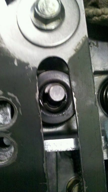
8) Compress the valve spring ensuring the valve is supported well inside the cylinder. You will need to compress the spring enough so you can remove the two wedge shaped keepers on the valve stem. If you cannot compress the spring enough, try tightening the rocker arm stud bolt several more turns to move the leverage point. With the two keepers removed, move the tool out of the way and remove the valve spring retainer and spring. Warning- these keepers are very small and may fall out by themselves as the spring is compressed. Do not let them fall into the motor. Using a tarp under your work area will help keep a fallen part from bouncing and aid in locating a keeper if it falls.
Compressed valve spring- keepers are loosened and can be removed:
Valve spring components- notice the keepers are very small:
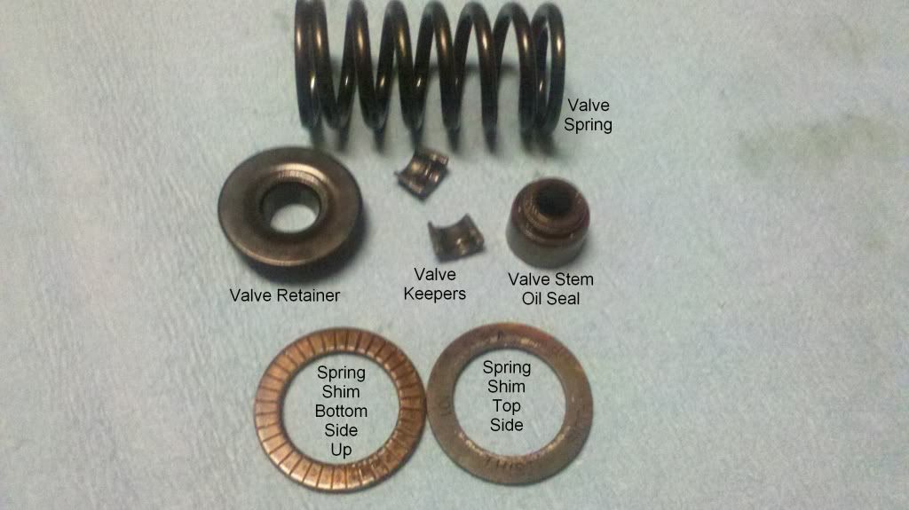
9) Install the valve spring shim over the valve with the smooth side facing up. Re-install the spring and retainer over the valve stem.
10) Use the compression tool to compress the valve spring and insert the keepers between the retainer and valve stem(small side of the wedge toward the head) Warning- these are very small parts and are easily dropped. When installed correctly the groove on the inside of the keeper will fit in the groove on the end of the valve stem. As you release pressure on the valve spring, the retainer will raise and wedge the keepers into the valve stem groove. If reinstalled correctly you will have ~1/4 inch of the valve stem exposed above the retainer. Repeat this procedure for the other valve on this cylinder.
11) Reinstall the rocker arms in the valves you removed them, torque the rocker arm stud to 100 in lbs (11 Nm). Move the crank shaft to allow you to remove the rope from the cylinder and bring the piston back to 1/4" past TDC on the compression stroke. Push down on the rocker arms and reinstall the push rods under the adjusters. Ensure the tip of the push rod is seated correctly in the cup on the top of the lifter at the bottom and in the cup of the adjuster under the rocker arm at the top.
12) Check/Set your valve lash to between 0.004-0.006. The feeler guage should slide between the rocker arm and valve stem with a small amount of resistance (like a knife cutting through a cool stick of butter). If you need to adjust the lash, loosen the 13mm nut on the rocker arm adjuster and use the T-40 torx to turn the adjuster screw to achieve the correct gap, hold the torx firm and re-tighten the 13mm lock nut.
13) Repeat for the other cylinder and take advantage of the higher RPM you are now able to turn without floating the valves.
Note- If available, an air compressor could also be used to pressurize the cylinder and support the valves during this operation.
The first RPM limitation on a stock motor is valve float at ~4400 RPM (different on each motor). Valve Float is a condition where the valves are opening and closing at such a high rate that the valve springs fail to fully close the valves for the cylinder, allowing them to float during the stroke cycles. This condition could possibly result in valve-piston contact and engine damage. To allow the motor to run at a higher RPM, you can add shims under the valve spring, increasing the spring pressure and eliminating the risk of valve float. Iron Mountain heads designed for higher RPM operation already have these shims installed (you will see them under the valve spring). BPS sells these shims as a High Rev Kit.
If installing CDI High Rev Coils (4700 Rev Limit) on a stock motor, you will need to install the shims to allow motor operation up to ~4500 RPM. Note- these shims from BPS are not just washers, they are specific thickness designed to add a precise amount of valve spring pressure.
Tools/Parts Required:
Tarp, 10mm Ratchet, Spark Plug Socket, Wooden Dowl, 5' length of 3/8 climbing rope (no loose fibers), shop rags, eye protection, Valve Spring Compressor tool, Valve Shims, and Torque Wrench. To reset the valve lash- 0.004-0.006 feeler gauge, 13mm wrench, T-40 Torx driver
Prepare your work area, there are small components involved so its advised to lay a tarp down under the motor to catch any parts if dropped.
1) Remove the spark plugs from both cylinders.
2) Remove the valve cover on one side of the motor. Engage the clutch or turn the crank shaft until the piston is on the compression stroke (put your finger in the spark plug hole until you feel the piston pushing air out of the hole on the compression stroke). Use the wooden dowel in the spark plug hole to gauge the piston position and turn the crank until the piston is 1/4" past top dead center. Both valves should be closed (slack on both rocker arms). Press down with the palm of your hand on the valve end of the rocker arm and move the push rod out from under the adjuster on the end of the rocker arm. Remove the rocker arm stud (10mm) and rocker arm and set aside the push rod with that rocker arm as a set. Remove the other push rod / rocker arm and set aside together so you can reinstall on the valve it was originally installed.
Push on the rocker arm to remove the push rod:

3) Reinsert the wooden dowel in the spark plug hole and engage the clutch or turn the crank shaft in reverse to move the piston in the cylinder to the bottom of its stroke.
4) Feed the length of rope into the spark plug hole. Tie a knot at the end of the rope so you do not loose it in the cylinder (just in case). The rope will support the valves so they do not drop into the cylinder or strike the piston when the valve spring is compressed.
5) Rotate the crank shaft forward until you feel resistance and the rope is fully compressed in the cylinder.
6) Insert a shop rag to completely block off the area in the head where the push rods go. Insert a piece of shop rag over the small oil drain hole in the front of the intake valve. This is important so you don't drop the small valve keepers into the motor.
7) Install your valve spring compress tool. There is a Briggs part number for this tool (PN 19347) or aftermarket tools from the auto parts store meant for small engines (note- most of the tools common at auto stores are intended for much larger valves and do not work well for this application). The tool is a length of stock that has a hole on one end and a larger hole/slot that will fit over the valve stem. Pictured here is an old trim bracket that works very well for this operation, but you can use anything that allows you to lever and apply pressure to the valve spring. For the tool pictured, insert a rocker arm stud bolt (10mm) through the hole on one end of the tool and hand screw into the hole for the rocker arm stud.
8) Compress the valve spring ensuring the valve is supported well inside the cylinder. You will need to compress the spring enough so you can remove the two wedge shaped keepers on the valve stem. If you cannot compress the spring enough, try tightening the rocker arm stud bolt several more turns to move the leverage point. With the two keepers removed, move the tool out of the way and remove the valve spring retainer and spring. Warning- these keepers are very small and may fall out by themselves as the spring is compressed. Do not let them fall into the motor. Using a tarp under your work area will help keep a fallen part from bouncing and aid in locating a keeper if it falls.
Compressed valve spring- keepers are loosened and can be removed:


Valve spring components- notice the keepers are very small:

9) Install the valve spring shim over the valve with the smooth side facing up. Re-install the spring and retainer over the valve stem.
10) Use the compression tool to compress the valve spring and insert the keepers between the retainer and valve stem(small side of the wedge toward the head) Warning- these are very small parts and are easily dropped. When installed correctly the groove on the inside of the keeper will fit in the groove on the end of the valve stem. As you release pressure on the valve spring, the retainer will raise and wedge the keepers into the valve stem groove. If reinstalled correctly you will have ~1/4 inch of the valve stem exposed above the retainer. Repeat this procedure for the other valve on this cylinder.
11) Reinstall the rocker arms in the valves you removed them, torque the rocker arm stud to 100 in lbs (11 Nm). Move the crank shaft to allow you to remove the rope from the cylinder and bring the piston back to 1/4" past TDC on the compression stroke. Push down on the rocker arms and reinstall the push rods under the adjusters. Ensure the tip of the push rod is seated correctly in the cup on the top of the lifter at the bottom and in the cup of the adjuster under the rocker arm at the top.
12) Check/Set your valve lash to between 0.004-0.006. The feeler guage should slide between the rocker arm and valve stem with a small amount of resistance (like a knife cutting through a cool stick of butter). If you need to adjust the lash, loosen the 13mm nut on the rocker arm adjuster and use the T-40 torx to turn the adjuster screw to achieve the correct gap, hold the torx firm and re-tighten the 13mm lock nut.
13) Repeat for the other cylinder and take advantage of the higher RPM you are now able to turn without floating the valves.
Note- If available, an air compressor could also be used to pressurize the cylinder and support the valves during this operation.